
Here we are, at the beginning of creating a simple flight plan that will help you become familiar with the C-Astral Pilot C³P software.
In this tutorial we will work in simulation mode. We will choose the location and then create the flight plan. After that we will simulate the flight.
IMPORTANT: Simulation only works like older AP. There are slight changes in procedure with newer AP system.
1. Install C³P
Install C-Astral Pilot C³P software. In case of any problems please refer to Install section.
2. Run C³P
Now you should be able to see Jump To Location dialog (opens automatically at the start of the program). In this dialog you will select the location of your flight plan.
For the purpose of this tutorial please select the default location (C-Astral) from the PREVIOUS list. C³P software will zoom into the desired location.
NOTE: In case you are not connected to the Internet you should input Lat Long coordinates of the place "45.902428, 13.877565".
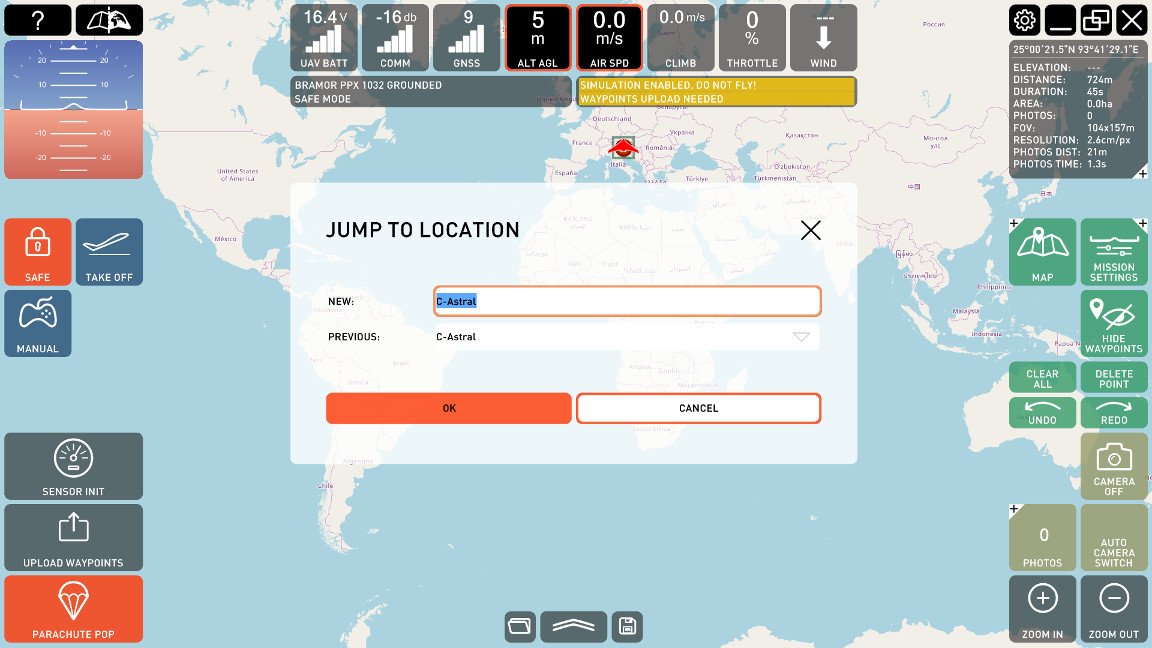 Location where you are going to plan flight mission. |
Simulation mode should be enabled by default.
NOTE: Please check speakers volume on your computer in order to hear audio messages.
Notice "Simulation enabled" notification on Log panel ( + audio).
 Log Panel - Notification. |
|
3. Take-off and landing settings
Once you are positioned on the desired location you should see the four circle markers in the center of the map. These points represent take-off and landing parameters for your UAV.
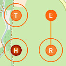 Home (H), Take-off (T), Rally (R) and Land/Parachute (L/P). |
In Take-off mode UAV will fly from launching position to Take-off (T) point where it will loiter (circle around) and wait for the next command. In Land mode the UAV will fly to Rally (R) point, descend and then fly to Parachute (P) point where the parachute will be opened. It will land in Land (L) point. |
Observe data on MISSION DATA PANEL. Observe Elevation field.
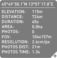 Mission parameters. |
On the Mission data panel check that Elevation is available. Digital elevation model is downloaded from C-Astral server and requires Internet connection. Otherwise you will see "Elevation: ---" which means that it was not possible to load elevation data for the visible map portion. WARNING: If Elevation is not available please refer to the chapter Digital Elevation Model. |
If Elevation is available altitude above ground level (AGL) and mean sea level (MSL) of Home, Take-off, Rally and Parachute points are visible in Flight Plan table as shown on the picture below.
For the purpose of this tutorial please use the current settings for these positions.
 Open table |
Click on the FLIGHT PLAN TABLE button to open the Flight Plan table. |
Right-click on the points on the map (waypoint) or left click on the table row opens waypoint settings dialog. For the purpose of this tutorial please use the current settings for these positions.
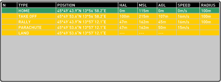 Flight Plan Table - List of waypoints with parameters. |
4. Draw a flight plan
Press DRAW button. This will open draw menu where you can choose from different drawing options.
Select AREA PTS button that will allow you to add area you are going to fly.
 Draw Menu - Area drawing mode is selected. |
Left-click on the map to add area points.
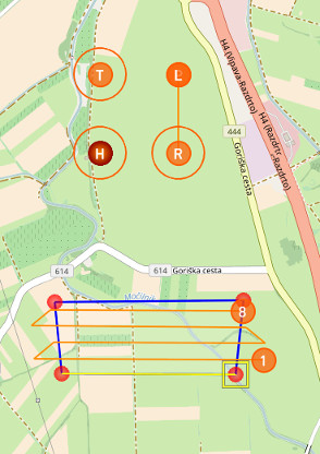 Simple Flight Plan - Using area drawing mode. |
Add 4 area points. In case you are not satisfied with the area use Undo/Redo buttons or press "Clear all" button to delete all. Notice that after the third point is added area is filled out with the flight lines. Area is recalculated each time a new area point is added to the map. BLUE lines represent area lines. ORANGE lines represent flight lines and define the path that the UAV will follow while flying above the area. ORANGE CIRCLE with a number inside represents a waypoint. There is a waypoint on each end of a flight line and in our example there are 8 waypoints altogether. The first and the last one in the sequence are marked with orange circles. Left-click/tap area line or area point to select it. Selected area line or area point is highlighted. You can move it to some other position. When an area line is selected and moved the flight lines are recalculated. |
TIP: Flight lines are parallel to the selected area line. To change the orientation of flight lines just select an area line (blue line) and slightly move it. The first waypoint is set near the side of the area which is closer to the position where the area line was selected with the mouse pointer.
 Mission settings. |
Select your mission (click on one of the area lines) and press MISSION SETTINGS button to inspect or change selected area mission settings. Waypoints parameters (altitude, speed, etc) are configurable in Mission Settings dialog. Mission settings dialog for the selected area is shown in the picture below. For the purpose of this tutorial you can leave the predefined values. |
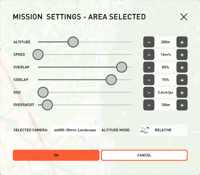 Mission settings dialog - ppX airframe.
|
Flight Plan table shows waypoint' altitude and speed parameters as well as coordinates and loiter radius if exists. UAV is going to fly at the altitude of 200 m above ground level (AGL) with the air speed of 16 m/s. UAV is flying in relative altitude mode which means that the height of the UAV is going to be adjusted for each flight line in order to maintain the altitude of 200 m above ground level.
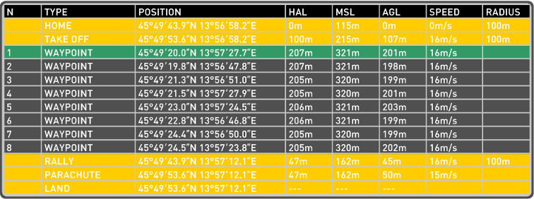 Flight Plan Table - Showing new waypoints created by drawing of area. |
5. Initialize sensors
Press SENSOR INIT button.
 Sensor Init. |
Before take-off you must initialize the sensors. This will calibrate the pitot tube, static pressure, set Home position and check the system for potential faulty readings. |
NOTE: The button is red and blinking warning you that you must calibrate the sensors. After calibration its color will become gray.
Press OK button. Sensor Calibration dialog is opened. For now just leave the default value (15 °C) and select OK.
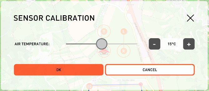 Sensor Calibration - Select current temperature and calibrate UAV's sensors. |
Notice "GNSS Home initialized" and "Pressure initialized" (+ audio) notifications on Log panel.
 Log Panel - Notifications. |
Notice "All sensors passed" notification on Log panel ( + audio).
 Log Panel - Notifications. |
6. Upload waypoints
Press UPLOAD WAYPOINTS button.
 Upload to the autopilot. |
Upload the flight plan to the UAV. NOTE: The button is red and blinking warning you that the flight plan is different from the one on the UAV. After the upload its color will become gray. |
Notice "Waypoints uploaded" notification on Log panel ( + audio).
 Log Panel - Notification. |
7. Take-off
Press TAKE OFF button.
 Take-off mode. |
After successful sensor initialization and upload of the flight plan you can take-off. |
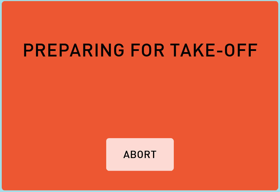 Information - Preparing for Take Off. |
When TAKE OFF button is pressed first message Preparing for Take Off is show. in real flight message ready for Take Off will be shown and after this the operator could pull the catapult release. |
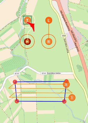 Take-off Mode - UAV loiters around T point. |
In take-off mode UAV will fly from launching position (in our example Home (H) point) to Take-off (T) point where it will circle around it and wait for the next command. |
Observe data on PRIMARY DISPLAY. You can monitor your UAV current altitude above ground level (AGL), air speed, UAV's climb rate, communication strength and GNSS signal strength, UAV's battery status, UAV's throttle and wind information.
 Primary Display - Monitoring primary flight data. |
Observe data on FLIGHT DATA PANEL.
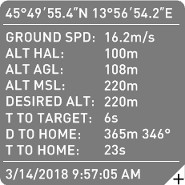 Monitoring flight data. |
Flight Data Panel (toggle panel) with additional information about the current UAV position. Observe current UAV's ground speed, altitude above launch position (HAL), altitude above ground level (AGL), mean sea level altitude (MSL), desired altitude, time to target (destination point), distance and time to Home point. Desired altitude of the UAV in T point is T point MSL which is 220 m in our example. UAV's target is Take-off point. |
8. Navigate
Press NAVIGATE button.
 Navigation mode. |
In navigation mode the UAV flies towards the destination waypoint (in our example towards the 1. waypoint of the area). Desired altitude of the UAV is changed to the MSL altitude of the 1. waypoint (Flight Data Panel). |
Take-off (T) point is not accessible anymore once the mode was changed from Take-off mode to some other mode (like Navigation).
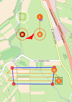 Navigation Mode - UAV flies towards the first waypoint. |
Currently active (destination) waypoint is highlighted with the green square (see picture). After reaching the 1. waypoint UAV continues to fly to each consecutive waypoint (destination waypoint is always highlighted with the small green square). After the last waypoint the UAV automatically returns to Home position and remains there until you select the next command. IMPORTANT: It is important that you monitor Primary Display data and Flight Data Panel during the flight and ensure safety/situational awareness. |
In the Flight Plan table destination/selected waypoint is highlighted with green color. In the picture below it is visible that the UAV is flying towards the 1. waypoint. MSL of the destination waypoint (waypoint towards which the UAV is heading) is the desired altitude of the UAV, visible on the Flight Data panel under DESIRED ALT field.
 Flight Plan Table - List of waypoints with parameters. |
Click on the 1. waypoint row in the Flight Plan table opens the dialog with the waypoint properties as displayed below. During the flight it is possible to press FLY TO button to direct the UAV to the desired waypoint.
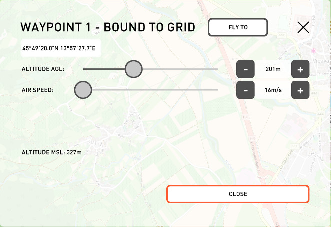 Waypoint dialog - Fly To command. |
9. Camera
If flying with the ppX UAS (default setting) camera will start triggering once the UAV has reached the 1. waypoint. Camera is triggering while UAV is flying over the area and is turned off when UAV is outside the area (automatic camera mode). Camera settings are explained in Photos section.
 Camera On/Off |
Camera triggering is enabled by default for ppX UAS. It can be disabled by pressing on the toggle button Camera On/Off. Camera triggering sound is enabled by default and you will be able to hear camera triggering. |
To show photos coverage press PHOTOS button, SHOW PHOTOS. To hide photo projection press SHOW PHOTOS again.
 Photos menu during the flight - Show photos |
10. Land
Press LAND button.
 Land mode. |
You can either wait for UAV to return to Home point and then press land command or you can press land during navigation mode. |
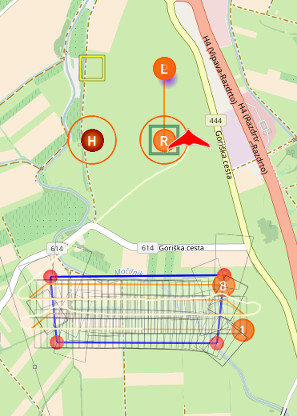 Land Mode - UAV flies from R point to P point and lands in L point. |
In land mode the UAV flies to Rally (R) point, descends to preset “brake” altitude and then flies to Parachute (P) point where the parachute is opened. The UAV lands in Land (L) point. |
When flying from Rally to Land point notice "Final approach" notification on Log panel ( + audio).
 Log Panel - Notification. |
When the parachute is deployed notice "Parachute deployed" notification on Log panel ( + audio).
 Log Panel - Notification. |
After landing it is important to save the photo's log file (OPH log file). After log file is saved (please check section Clear Log) it is safe to delete it from the UAV. Press PHOTOS button, CLEAR PHOTO.
 Photos menu after landing - Clear Log |
